A few weeks into my training at access: technology, I was lucky enough to meet one of our long-time clients Jack. I joined Mike at an appointment where we were swapping out some components of Jack’s computer setup, one of which being a piko switch programmed as his Surface Pro computer ‘Left click’.
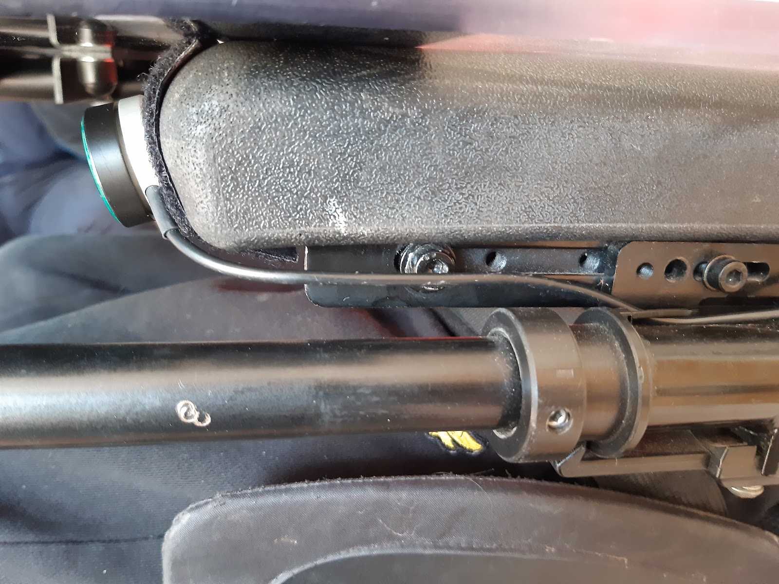
The position of the switch was right on the end of Jack’s armrest, which from a postural perspective was ideal to ensure a comfortable and functional use of the switch without crossing the midline. That being said, attaching the plastic switch and its trailing wire to a foam armrest was a little more of a challenge!
Velcro is a truly wonderful invention, one that I’ve found already in this role is something you can’t go too long before finding a new use for. While an extra-strong Velcro was somewhat doing the job of attaching the switch to Jack’s armrest, I’m sure Mike wouldn’t mind me saying that it wasn’t the most elegant of solutions … the Velcro was peeling away, looked a bit out of place, and also didn’t allow the switch to be set perpendicularly to the armrest, which posturally would be preferred. This got me thinking about how we could streamline this attachment, utilising the hardware of Jack’s chair to attach the switch in a more refined manner.
Step 1 – Acquire the necessary tools!
To create a solution that worked uniquely for Jack and his equipment, it would probably need to be designed from scratch. We decided to go ahead and purchase Computer Aided Design software (SolidWorks), and a desktop 3D printer to really push the envelope on what solutions we could provide both for Jack and all our clients! After some setup configurations and calibrations, we set to print our first model – which was of course prototype A of Jack’s Switch Mount! We made sure to film the whole thing of course, see the jazzy time-lapse below!
Step 2 – Testing the Prototype
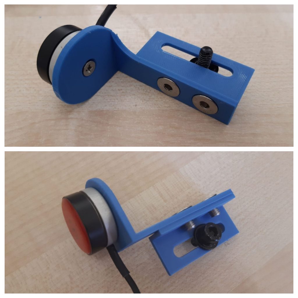
The first design was a two-part model, aimed to attach a mounting plate to the metalwork underneath the armrest of the chair. 3D printing at this scale doesn’t favour threaded components, so having 2 pieces allowed us to attach them to the metalwork using nuts and bolts. It also gives an improved quality to print these pieces separately, as the accuracy and finish of 3D printed parts increases significantly when shapes are simplified a little.
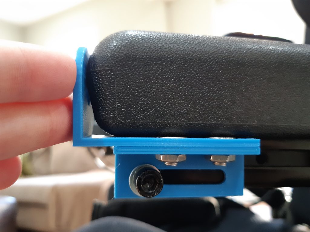
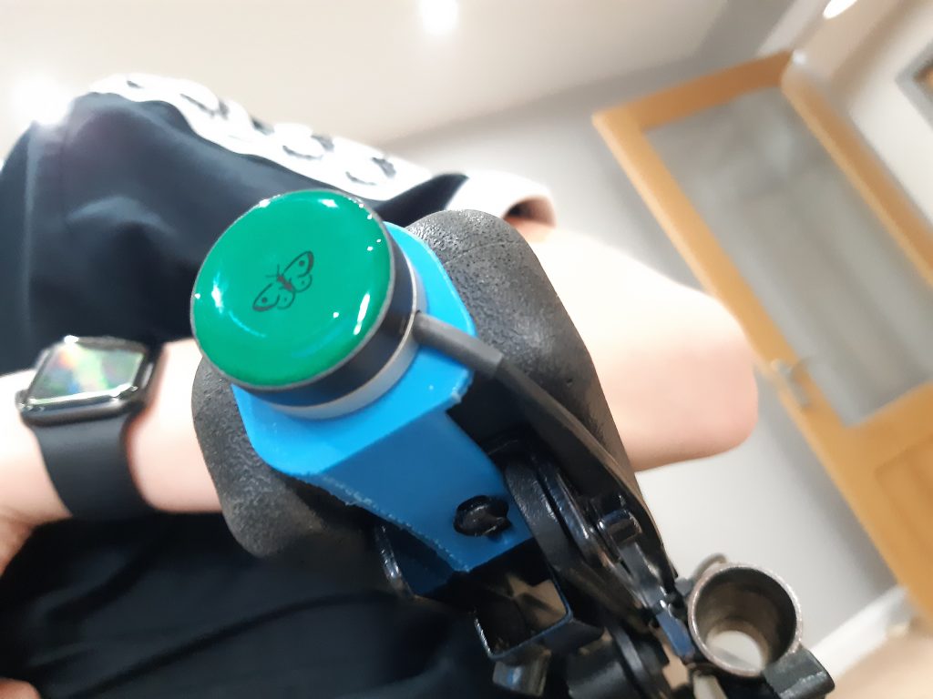
This particular design was certainly a rough attempt. Another lesson learnt from this challenge was to always bring measuring callipers to appointments – you truly never know when you’re going to need some pretty specific dimensions! That being said, I expected it to be slightly off in terms of where the switch would sit. It certainly followed that expectation, and in fact ended up demonstrating that the approach likely wouldn’t work as we had hoped. In the image below, you can see that I am in fact holding this in its ideal position, as the dimensions of the interfacing pieces aren’t allowing it to be attached to the metalwork of the chair. Often with prototype work like this, it takes physically placing something in-situ to really know whether it will work. Computer Modelling is a triumph, but nothing substitutes a hands-on test! We tried some other ideas using the components we had (and took some proper measurements), and went for a new, more refined approach.
Step 3 – The Improved Prototypes
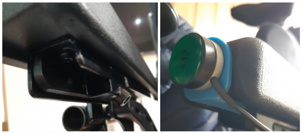
Having looked into the intricacies of Jack’s chair a little further, we decided to change tact and attach the switch mount to the chair from a different point. A screw currently attaching the foam arm rest to the metalwork below provided the perfect interface, as it was close to the final mounting position, and also hidden underneath the arm rest and less likely to interfere with Jack’s use of his chair. The aim was to add the plate to this bolt, and attach it back together as before but this time holding the switch.
Success!
Following on from last time, to make sure we maximised time on site to really figure this out, I made a few versions of the same design, each with slightly different dimensions (in case of any anomalies or missed measurements!). After a quick file down of one of the edges (another tool swiftly added to my kit bag after visit number one), we secured Jack’s switch to its mount, and the mount to his chair. Jack was happy with the position, and it felt stable and secure in its place. Mounting the plate in this way allows the main force applied to the switch to be taken by the foam armrest, so getting it as close to this surface as possible was our target.
With Velcro gone, we left Jack with the mount attached, tasked with giving us his honest feedback on how things worked out over the following couple of weeks.
Step 4 – Finale!
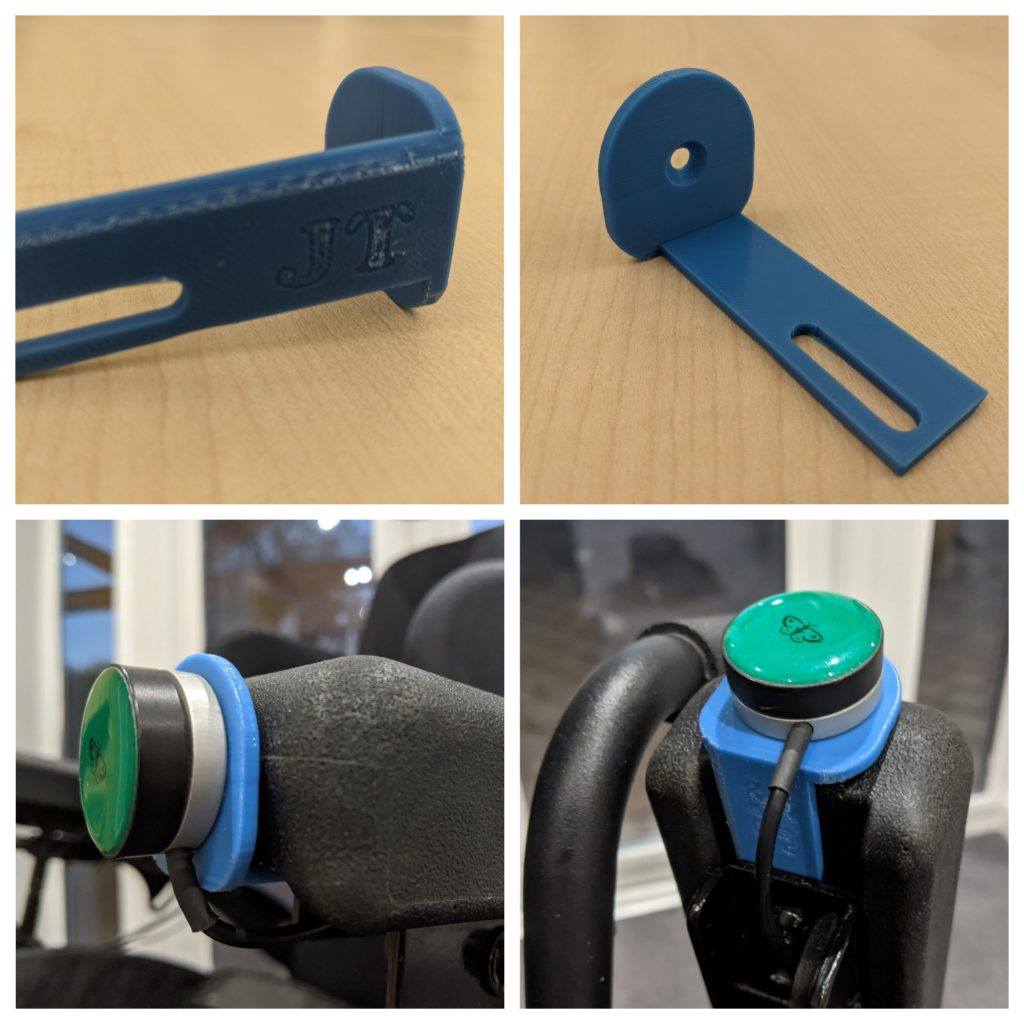
Some final amendments were required to the latest prototype, mainly to adjust the width of the mounted section in line with Jack’s chair (just to cover the excess filing we did on-site). The finishing touch, as per Jack’s request, was a bit of personalisation! Why not customise an already bespoke component?! With his initials embossed into the design, and the printer set to blue filament, Jack’s final designs were on the way.
And here we are, with the switch mounts fitted to Jack’s chairs for use at home and school. Overall, our goal to streamline the attachment of the switches (and make the whole assembly look a little more desirable) was achieved. Most importantly though, it was an outcome that Jack found functional, aesthetic, and was driven by his ideas and inputs to the process.
Sharing technology which might not ordinarily be classed as assistive is just as valuable in empowering users to champion their own learning. The accessibility of 3D printing is a world away than a few years ago, and there is certainly more to come, but I’m certain that it will continue to grow into something as day-to-day as computers themselves.
With both prototype design and 3D printer programming all stemming from software solutions, I’d like to think that using assistive technology to make assistive technology is the way forward …